 LinITX Blog Ubiquiti & MikroTik Wireless Networking Experts

(This how to also applies to 2.4GHz Ubiquiti Equipment)
We are often asked how to make building to building or ‘point to point’ wireless links. This HowTo explains how to use Ubiquiti Nanostations to make a transparent link.
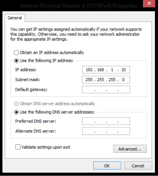
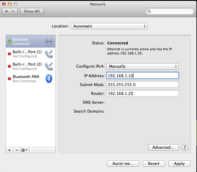
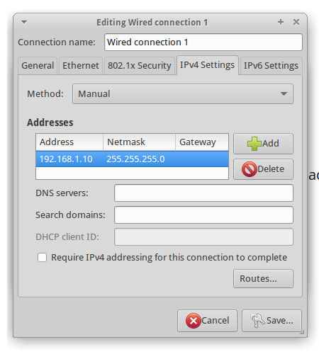
The first port of call for configuring any Ubiquiti device is to manually change your systems IP address in order to communicate with the Ubiquiti equipment, in this HowTo I will be using 192.168.1.10 as my system IP (note that many Ubiquiti devices are configured on 192.168.1.20 from the manufacturer by default).
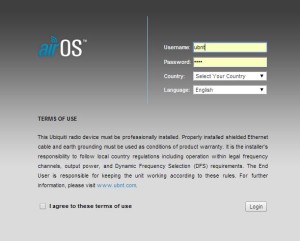
In this HowTo the 2 NanoStations will be named NanoA and NanoB, (do not plug both NanoStations into your computer or switch at the same until Configuration is complete on each one). Once IP configuration is done on your System PC (see above Images) plug NanoA into your system and you will now be able to see the NanoStation by typing https://192.168.1.20 into any browser.
The Manufacturer’s default Username of ‘ubnt’ and Password of ‘ubnt’ should be entered in this point as well as the country in which the NanoStations will be operating in. Once logged in you can begin to configure NanoA with a more suitable IP for your network, this is done through the network tab of NanoA’s AirOS interface via your browser. The IP can be set to Static or to obtain one via your DHCP server but for the purposes of this HowTo, please make note of the NanoStations IP address for configuration, for this how to the NanoStations will be configured, as follows.
- NanoA 192.168.1.30
- NanoB 192.168.1.40
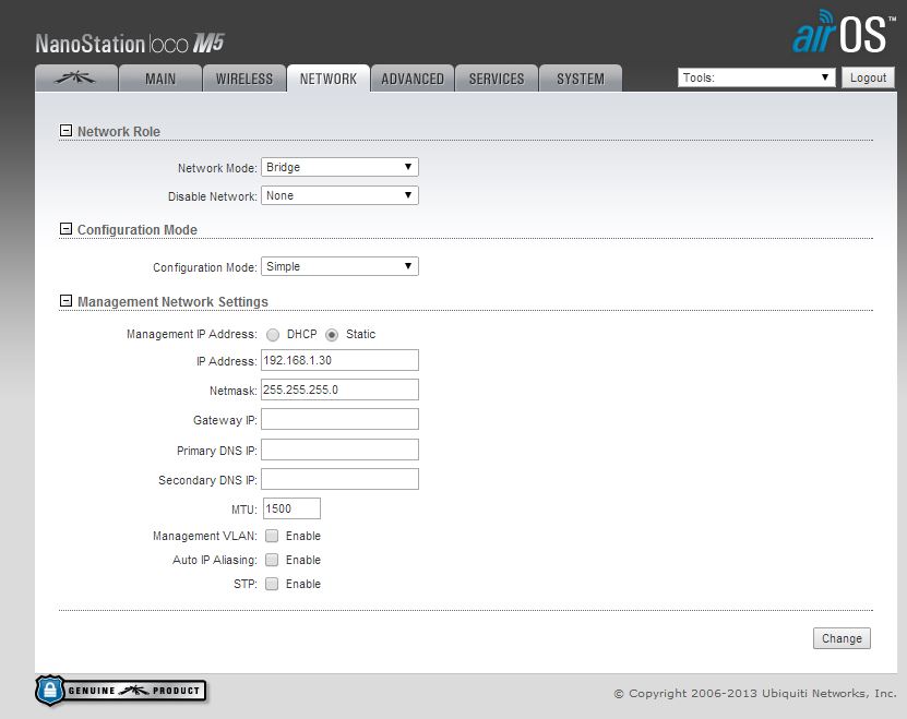
Once you are happy select Change followed by Apply which will reboot the NanoStation and apply the settings, or select Test to temporarily apply the new settings for 3 minutes which will automatically change back if not applied within the allotted time.
The Test feature is a good idea as it will allow a troubleshooting window to reconnect to the NanoStation with the Static or DHCP details previously configured, after 3 minutes with no apply the settings will revert back to the default (192.168.1.20).
Repeat this step for Nano B making sure it gets its own unique IP address.
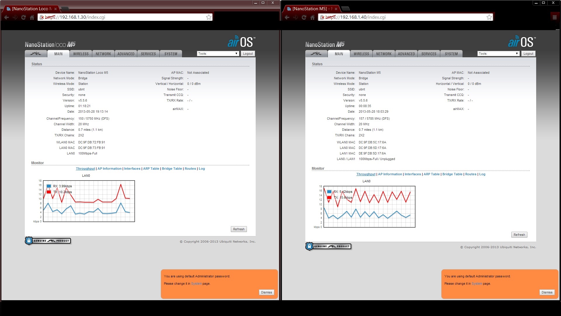
You should now be able to connect to both stations simultaneously on the individual IPs.
For the next stage of wirelessly bridging the 2 NanoStations we need to decide on an operating frequency, the AirOS comes equipped with a Spectrum Analyser (AirView) which is extremely helpful for finding a clear operating channel to bridge these devices on.
Once you found a good frequency it’s time to start configuring the Nano’s in bridge mode, to do this I designated NanoA to be my station and Nano B to be my Access Point.
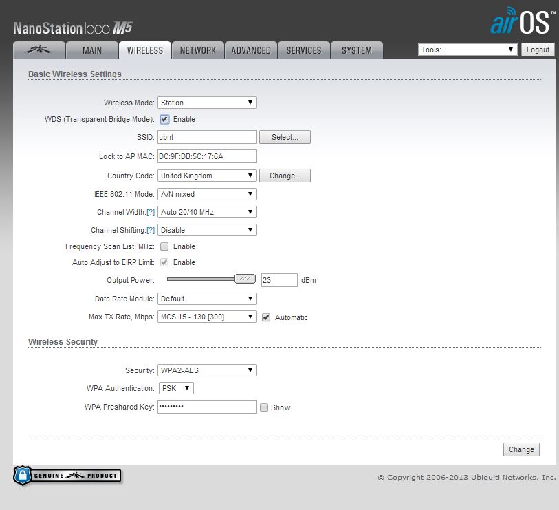
Since by default the NanoStations are in Station mode not much configuration is needed for NanoA but I will apply some security to the connection, it is recommended to use WPA2-AES in order to achieve the highest level of security and maximum possible throughput.
By default the NanoStations will be set to use Auto 20/40Mhz Channel bandwidth, I will be using 40Mhz for this HowTo (New Wireless AC or 802.11 AC will require 80Mhz channels for max throughput). It is best practice to use the smallest channel width for your chosen application, eg for smaller throughput start at 20 MHz channel width
You should ensure that ‘WDS (Transparent Bridge Mode)’ is selected on NanoA to ensure full Layer 2 communication with the other side of the Bridge.
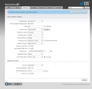
Now on NanoB, select the wireless tab on NanoB’s airOS interface and change wireless mode to Access Point, the channel width is then also manually selected here to 40MHz (New Wireless AC or 802.11 AC will require 80Mhz channels for max throughput) along with the chosen operating frequency. It is best practice to use the smallest channel width for your chosen application, eg for smaller throughput start at 20 MHz channel width
For test purposes I am using an Ofcom Band A indoor frequency which operates on a lower power level than other Band B or C frequencies. For connecting two buildings, these will be outdoors, therefore you will need to chose a frequency between 5500 and 5840MHz (2.4GHz equipment will be on different Frequencies).
Wireless security should also be set again here, use WPA2-AES for best security and maximum throughput. Ensure that ‘WDS (Transparent Bridge Mode)’ is selected on NanoB to ensure full Layer 2 communication with the other side of the Bridge.
To finish the Bridge off, log back into NanoA and select the wireless Tab followed by select next to the displayed SSID. This will open a new window and display all available Access points that are available.

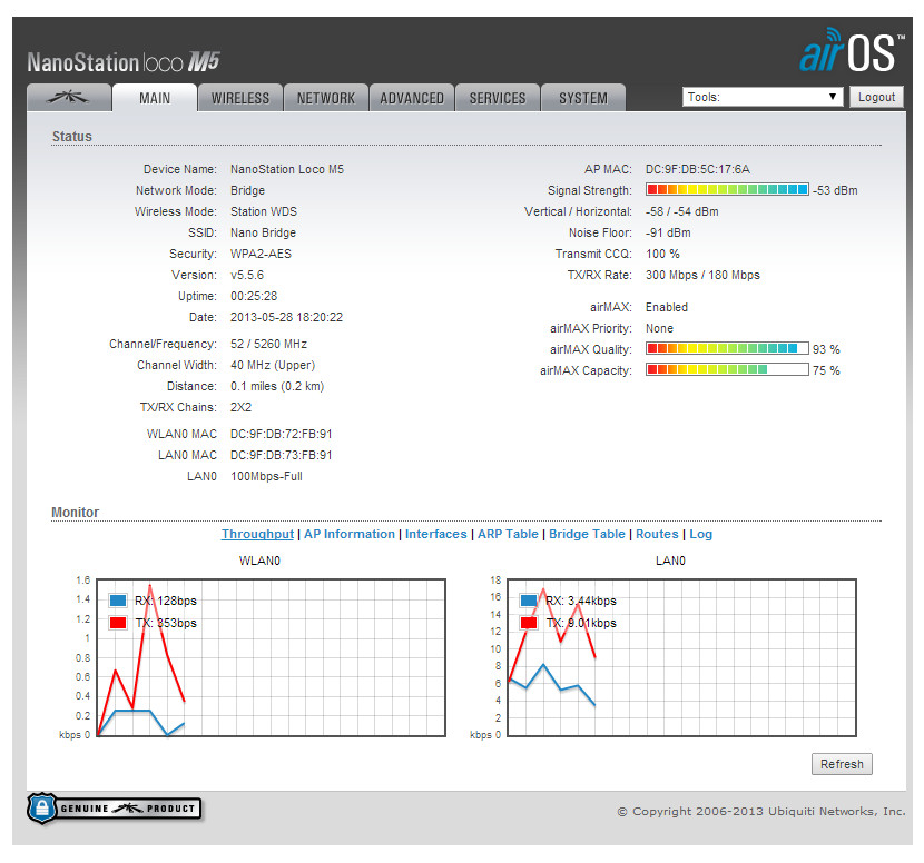
As you can see from the image our Nanostation is listed and awaiting connection, select the Nanostation using the radio button on the left (Leave ‘Lock to AP’ Blank), apply the settings for NanoA and after a short reboot NanoA and NanoB will be bridged. If the two radios are still connected to a commonly connected switch, a broadcast storm will quickly ensue, therefore ensure that the two radios are not connected via Ethernet cabling at this stage.
The wireless bridge can be easily tested before placing the 2 Nanostations in their respective location by simple removing NanoB’s Lan connection from the switch ensuring that the POE connector is still connected to NanoB then attempt to connect to NanoB’s interface whilst connected directly to NanoB or visa versa. In some cases it may be worth reducing the power output of the Nanostations to improve on Airmax quality and Capacity, this is only applicable to very short links.
The image below shows the test PtP link I set up with both stations only running at 4dbm over what is at best a 10m range with an Airmax quality of 93% as opposed to the quality of 52% I received whilst running at high power. This really does prove that power isn’t everything and you should calculate the optimum power you need to acheive the best possible quality link at any range.
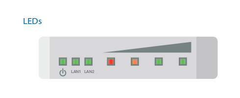
Now the 2 NanoStations are bridged they can be placed in their respective locations and fine-tuned for best connection using the LED lights on the rear to help with placement adjustment.
These point to point bridge links can be achieved with a number of Ubiquiti AirMax products with a variety of different mounts to choose from.
Although Ubiquiti can achieve some very high ranges for its equipment it must be noted these ranges are the maximum and throughput will reduce with distance. From our own experience here at LinITX and in conversation with other wireless ISP’s we have put together the table below which states the Ubiquiti products and a recommended range that will give you good throughput.
Desired Range Recommended Product
0-500m Loco Nanostation
0-1Km Nanostation
500m-3Km PowerBeam 22
1Km-5Km PowerBeam 25
3Km-10Km PowerBridge
(The above are approx. distances only)
For indoor/Outdoor PtP you will need a pair (x2) of Nanostations.
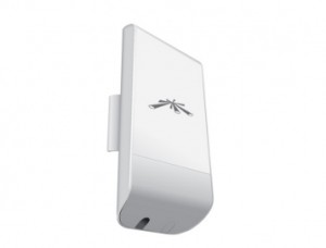
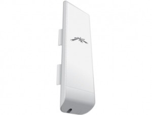
Ubiquiti Loco M5 | Ubiquiti NSM5
Various mounting options are also available
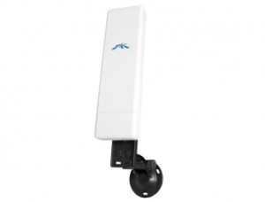
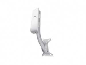
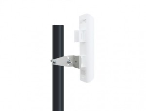

Windows/Wall | Universal Arm | Pole Bracket | Nano Bracket
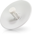
If you require some more range we also supply the Ubiquiti Powerbeam range


Thank you for this, it is a very helpful step by step process.
What is the process for bridging 2 stations to one AP? Both stations are in a straight line with the AP.
many thanks
I’m planning to implemented multiple PTP link, but l dont want the link to be transparent, can you let me know step by step how l can set up vlans so they can propagate to each other using the OSPF