A typical wireless broadband provider/WISP usually has multiple radios, each with their own POE connection.
Here’s a way of providing Gigabit POE with the ability to power cycle individual radios:
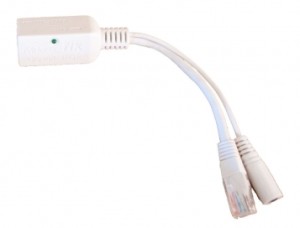
For Gigabit POE we use a MikroTik RouterBoard Gigabit Passive PoE Injector:
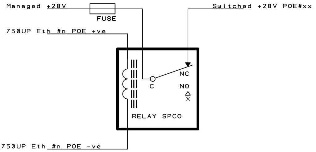
Each POE injector plugs into the main router and has power fed to it from a single 28V PSU via a relay, i.e. there is one relay per POE injector.
The relay allows us to control the power to each POE injector and defaults to providing power in the NC position. So to turn off the power on POE injector #1, relay #1 coil must be energised, for POE injector #2, relay #2 coil must be energised and so on. The diagram below helps explain what we’re doing:-
“Managed +28V” in this case means the 28V is supplied by a PSU with automatic switch over to batteries in case of mains power failure.
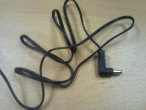
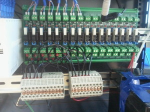
“Switched +28V” is the controllable power into each POE injector. We connect it to the POE injector using a standard jack lead (see below) and some DIN rail mounted connector blocks (see later on):
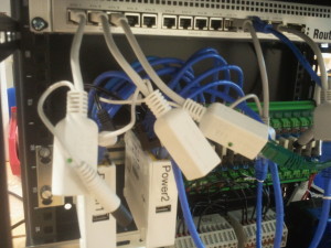
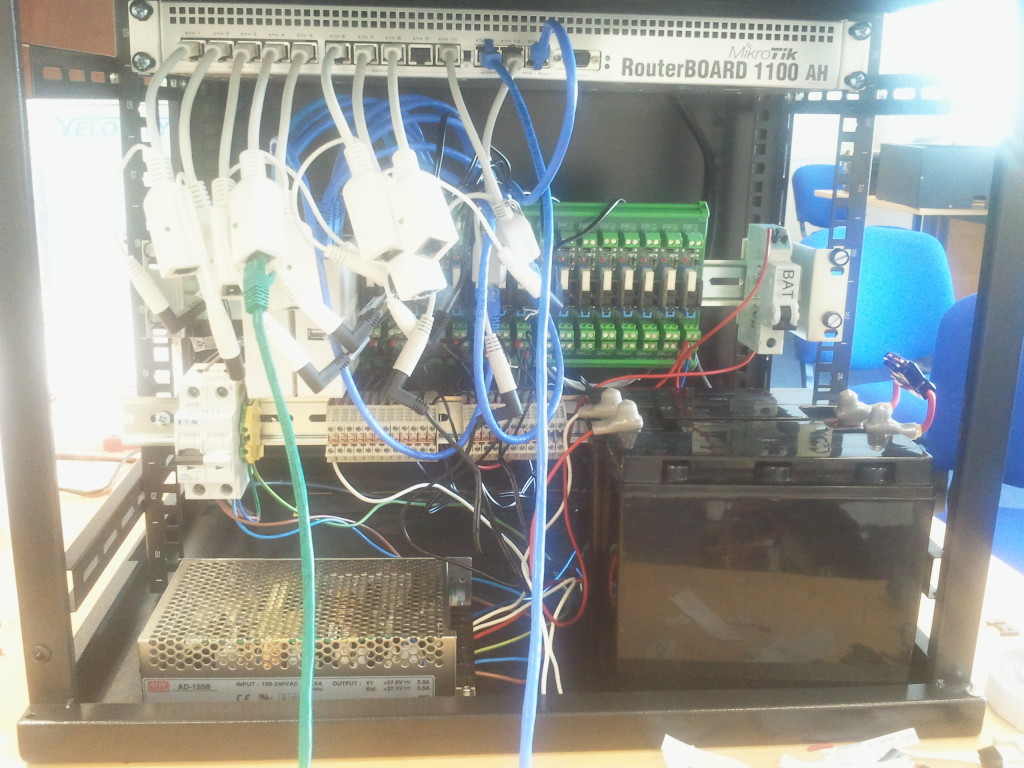
PoE injectors are shown below connected to the main router in the rack:
As you can see we decided on a 19″ rack with a DIN rail for the POE power management, and a DIN rail mount kit was added to 750UP as follows:
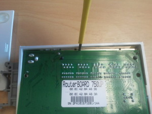
1. Gently ease off the back of the 750UP
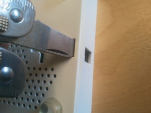
2. Lift up the bottom edge of the circuit board and then as shown above, gently prise the board from away from the top edge (the edge with the connectors)
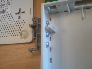
3. Drill 3 holes for the screws and fit the DIN rail clip
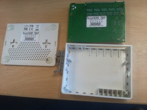
4. Ready for reassembly.
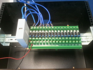
5. Mount it on the DIN rail. Shown below is a DIN rail mounted 750UP with 4 connections to a 16 Channel DIN Rail Relay Module (i.e. room for expansion). Each relay is separately fused!
6. A Second DIN rail is added to cope with the 0V and +28V interconnects:
Power Supply
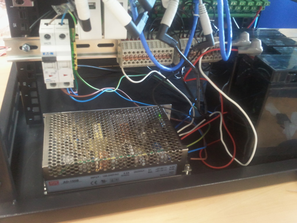
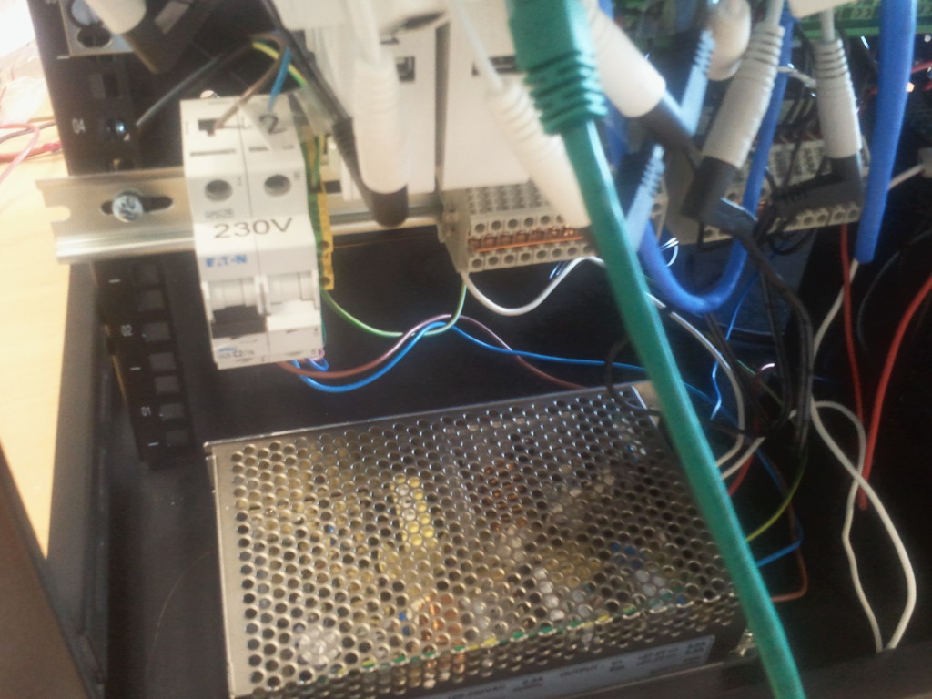
We have used a Mean Well AD-155B, which is 155W PSU with 28V DC output, 230V AC input and battery trickle charge circuit:
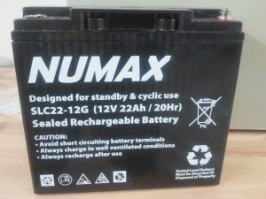
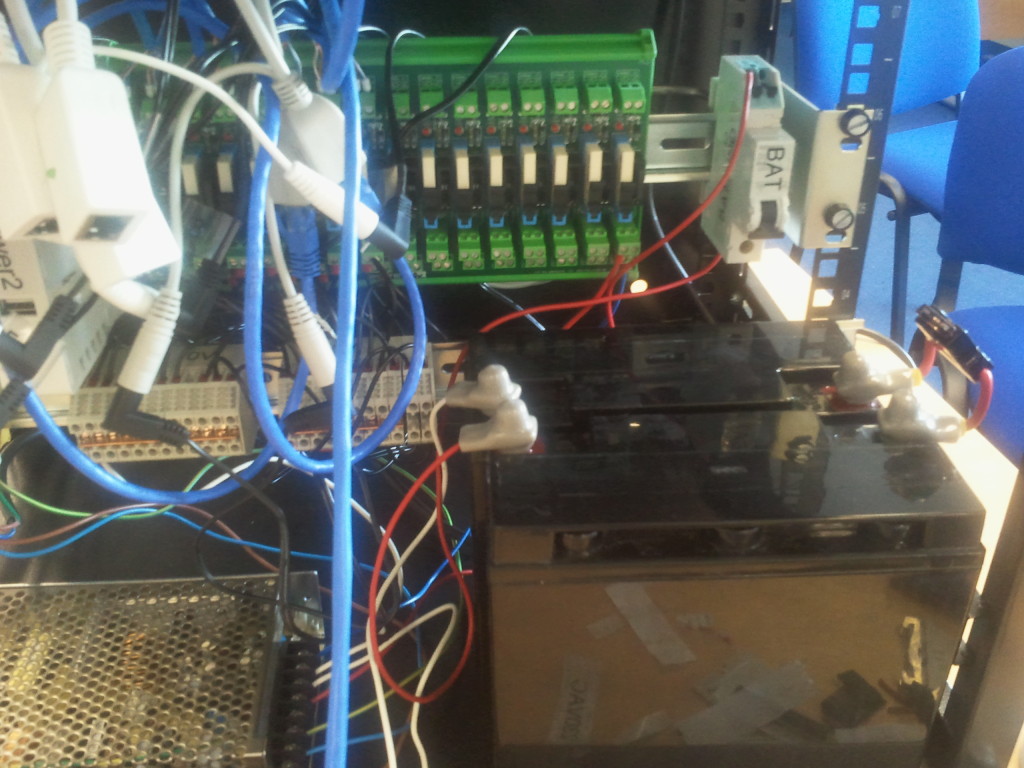
Main 230V AC is fed through a MCB which is also handy for switching off the mains power. A second isolator is provided for the batteries making it easy to replace them. We use two sealed lead acid 12V batteries in series to provide a minimum 24V DC backup . The batteries also have a 7.5A auto fuse inserted in series for extra protection.
Fully assembled rack:
 LinITX Blog Ubiquiti & MikroTik Wireless Networking Experts

