Need to know if a link distance is possible?
Want to get an idea of predicted throughput?
Ubiquiti’s airLink is a fantastic tool, if used correctly. There are some intricacies to using airLink correctly in the UK. Below we will explain step by step, how to model your prospective link whilst staying Ofcom compliant.
Firstly – arguably most importantly – Output power.
In the UK there are various power limitations on the 5.8Ghz spectrum. The spectrum frequency range is between 5150 and 5850MHz. The OFCOM standard for UK Operating channels split across 3 “bands”:
- Band A – 23dBm / 200mW
- Band B – 30dBm / 1000mW
- Band C – 36dBm / 3891mW
The maximum EIRP limit (Effective Isotropic Radiated Power) is dependant on which band is used. (detailed below).
Band A – (5150 – 5350 MHz)
Indoor Use Only
Band A is typically only used for indoor 5GHz applications such as Home/office WiFi Networks.
The maximum EIRP for Band A is 23dBm / 200mW.
Band B – (5470 – 5725 MHz)
Indoor and Outdoor Use
Band B is used for indoor and outdoor 5GHz applications, like indoor/outdoor Routers/APs and lower powered/ short range PTP devices.
The maximum EIRP for Band B is 30dBm / 1000mW.
Band C – (5725 – 5850 Mhz)
Outdoor Fixed Wireless
Band C is used for long range Outdoor PtP (Point to Point) or PtMP (Point to MultiPoint) wireless connections. Used mostly by WISPs (Wireless Internet Service Providers) and is a Licenced band.
The maximum EIRP for Band C is 36dBm / 3891mW.
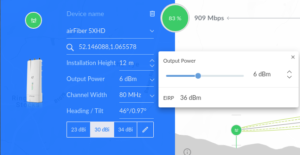
Working out EIRP is simple. airLink can do this for you with an easy slider (pictured below). EIRP (dBm) = Output Power (dBm) + Antenna Gain (dBi).
Band C requires a “Lite Licence” known as the Fixed Wireless Access Licence. The licence can be obtained directly from Ofcom. More information can be found here.
Modelling your Link:
Modelling you link in airLink is easy, Below is a step-by-step example of a simple PtP link.
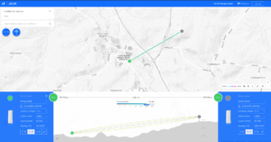
A complete link.
The appropriate radio, antenna, channel width and EIRP have been entered. The green lines represent unobscured Fresnel zones as well as a clear central line of sight.
The estimated maximum throughput (based on the distance, signal strength, clearance, channel width, gain and modulation rate) is displayed in the centre.
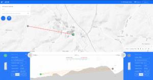
The orange/red lines represent obscured Fresnel zones as well as no line of sight.
Link not possible (based on heights of the radio set on each end and terrain obstruction). Only terrain height is taken into account. Trees and buildings will not be factored into clearances.
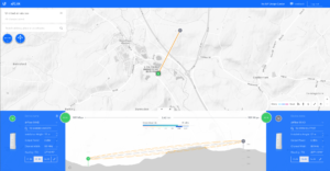
A partial obstruction.
The orange lines represent obscured Fresnel zones However, line of sight is obtainable.
This link would function but at a reduced speed with low reliability.
Entering your settings:
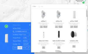
Selecting your device.
Pick the Ubiquiti radio you plan to use. Antenna options for that radio will then appear at the bottom (dBi values show here).
Setting the correct EIRP.
As mentioned above, you will need to select the correct EIRP value depending on the band/license. Once the Antenna and Radio are selected use the slider shown here. (Band C show in example)
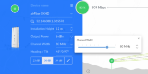
Optimise your channel width.
The channel width dictates the space within the frequency you will require/use. It effects how much data can be passed (imagine adding lanes to a motorway, the more lanes added/the wider the road, the more traffic that can flow). As well as the distance that can be achieved by your link. Spreading the same broadcast power over a wider area will reduce the total distance it can travel. Reducing channel width can help increase the total link distance. As you increase the channel width the received noise will also increase with it, this will reduce the SNR (Signal-to-noise ratio). Balancing the channel width to suit your needs is an important aspect of optimising your link.
Get all this right and you will end up with a healthy and reliable wireless link. However, 5Ghz can be effected by outside interference such as Weather stations, Ports, Airports and even other 5Ghz links. Ensure you have adequate spectrum space available when deploying your link by performing a spectrum scan. A feature build into Ubiquiti airMax products.
Looking to purchase AirMax products and are not sure which to choose? Call our technical team on 01449 724255 or email shop@linitx.com for assistance.
 LinITX Blog Ubiquiti & MikroTik Wireless Networking Experts

