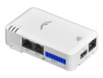
 The mFi range of products are a somewhat unusual diversion from Ubiquiti’s core networking products. Although they are networked devices their primary task is to perform and assist with building automation. The range consists of ‘m’ class devices, which do all the communications. The mPort can have up to 3 sensors connected to them. These ‘m’ class devices run Linux so you can ssh into them using the default username and password of ubnt/ubnt if you want to run them in standalone mode. LinITX hold stock of the mFi range so it’s available for next day delivery* if you’re eager want to try it out.
*Next day delivery for UK Mainland.
mPort
Provides access to a variety of sensors and relays. Up to 3 individual sensors are available in total but only one digital I/O is provided and that is included in the maximum sensor count.
mPort Serial
Provides a remote serial connection allowing remote serial devices to connect to the management software or for a terminal session to be opened from the management software.
mPower
The mPower comes in three guises but essentially they are all the same and just provide a different number of individually switchable ports. The mPower Mini has a single port, the mPower has three ports and the mPower Pro has eight. The big disadvantage of these is, unfortunately, the use of US style power sockets. Certainly for the Pro model it would have been better to use IEC style connectors.
What’s really interesting about these devices though, is that as well as having wired ethernet they are also WiFi (b/g/n) capable. This means you’ll be able to use these anywhere that you have a power socket available. The mPort Serial comes with an attachable antenna and external socket too. During setup, since the mPorts are all shipped with the same IP address, we configured them via the hard wired ethernet port to use their wifi to connect to the main system. Provided you use the same username/password combination on both of your management systems you should have no issues configuring devices like this.
Sensors
There are currently four different types of sensors available, although the movement sensor does come in both wall and ceiling mount versions. The sensors use CAT5 cable to connect to the mPort’s sensor ports, which are coloured blue. Although the connectors are CAT5 they are in no way network capable.
Door sensor – Is a simple reed switch that can be daisy chained, however, daisy chaining will simply cause a single ‘some event happened at this location’, effectively reporting as a single sensor. The Door sensor is wired to the I and O inputs on the provided terminal block and then plugged into the third sensor port.
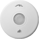
Wall/Ceiling sensors – The Wall and ceiling sensors use both infra red and microwave sensors to determine motion, although this is configurable via jumpers. You can also configure whether the LED lights up on detection, this is off by default.
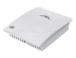
Temperature sensor – The temperature sensor returns, obviously, the current temperature in a particular location. Temperature reporting can be in displayed in Centigrade or Fahrenheit from within the management software.
Current sensor – The current sensor can report the electricity used by a piece of equipment. The loop on the sensor opens up and the wire is slotted in and then the loop is closed. However, you must only put either the live or neutral wire in the loop, not both. This means that there’s no quickly slipping in a power cable to measure a device’s usage.
Software
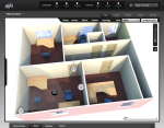
The management software is written in Java giving the freedom to install and run it under Linux, OS X and Windows. The software has no traditional GUI but provides the interface via your modern web browser. The interface itself makes heavy use of javascript to give a fluid and reactive experience. You can add schedules so that, for example, motion sensor triggers only occur at particular times of day or night. You can also make triggers conditional based on other events. So, for example, you could require the triggering of two different motion sensors before you send an alert email. Much like Ubiquiti’s other management applications, if you’ve use them you’ll see the resemblance, you can load your own floor plans or 3D renders and position the sensors appropriately on them.
The management software uses MongoDB for backend storage and although using a 32-bit OS does work it is not recommended. Depending on how many sensors you have you may hit the 2GB size limit of the database imposed on 32-bit systems.. Although 32 bit operating systems are not officially supported Ubiquiti have said that they will not actively block the use on such systems.
The biggest issue with the mFi management software is really the lack of an API which would allow the software to talk to third party systems. As it stands the mFi system runs in isolation which isn’t really appropriate for integration with other systems. Ubiquity have said that they are building Android and IOS client applications so there is a glimmer of hope for an API.
There is of course no reason you could not use the method described in the section below to bypass this limitation but this involves extra work and effort and introduces its own issues.
Hacking
The mPort devices are running Linux and are using dropbear as the ssh server. If you haven’t used the management software and adopted your mPort device you can use ssh to login using the default username and password of ubnt. However, if you are using the management software then you’ll find that the username and password for ssh match your login to the admin software.
Once you’ve made an ssh connection you will find a cfg directory in there you’ll find various config files that tell you what port a sensor is plugged into. If you cat the file named config_file you’ll be able to see which sensors, if any, the system thinks you have. Below is a sample where a temperature sensor is plugged into port 1.
port.0.sensorId=50559f7dca9bb0e4385dfde4
PWR.0.volt=12
AI.0.sensorId=50559f7dca9bb0e4385dfde4
AI.0.model=Ubiquiti mFi-THS
AI.0.label=Temperature1
AI.0.conversion=xyz*30 - 10
AI.0.rep_analog=1
AI.0.analog_tag=temperature
AI.0.sum_tag=degreeHours
For a temperature sensor we can look in /proc/analog and extract the readings. There are a few of things to note. AI.0 appears to actually be /proc/analog/ai1 there’s no ai0 in /proc/analog. You need to check that the port is enabled for reading, you can check by looking at /proc/analog/enabled and checking that the value returned is 1. If not simply echo a value of 1 to it. The value returned from a cat of /proc/analog/ai1 is not the actual temperature, you’ll probably see a low number, for example 1.003. This is where the AI.0.conversion line form the config_file comes in. That line is the conversion formula for getting the actual result.The xyz represents the value read from the sensor, so as an example:
#cat /proc/analog/ai1
1.003
Since our formula is :
xyz * 30 - 10
our actual temperature is
1.003 * 30 - 10 = 20.09
Incidentally, my first instinct was to look at emulating the management software using apache and an alias to /inform however the content and expected return values need to be encoded/encrypted. This is certainly worth exploring more since any key used must be on both the mPort and the server and makes for a much simpler extraction of the data for integration into other systems.
There is a possibility to build your own sensors, for example hooking up an AA battery to pins 3 and 6 of the RJ45 connection, or A+ and A- of the terminal block would allow you to return the voltage from the /proc/analog/ai<x> port. With a fresh battery it should read around 1.5 volts.
 LinITX Blog Ubiquiti & MikroTik Wireless Networking Experts







Good day,
Can I get this device with a wireless antenna to make a wireless link for remote data transmission over a distance of 2km.
Regards
You probably already found out but I would advice a Nanostation. Connect the mPort to the secondary ethernet port, using PoE pass-through would do the trick.
Hi, have you found a way to control power output or digital output from command line?
Some info is on wiki http://wiki.ubnt.com/MFi-Custom_Sensors but all is driven using gui.
regards
I’ve got it 🙂
in folder /usr/www/mfi is test.sh that makes it
for example to generate 3 second 12V pulse on power you can do
ssh ubnt@192.168.0.20
echo 0x152C70 > /proc/gpio/sr_val
sleep 3
echo 0x100000 > /proc/gpio/sr_val
exit
12V is present for 3 seconds on port 3 between G and P pins
Sima,
Have you found a way to turn on 12v to the RJ45 1 and RJ45 2?
Have you found a way to apply 12v on the RJ45 1 and 2 ports?
You can connect up to 5 door switches as each mFi Port has 2 IO pins