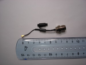
We were recently asked by a customer, why would an equipment manufacturer place Ferrite Beads on a coax cable pigtail? Also, should all pigtails have RF Ferrite beads? The answer is actually quite simple, but let us first cover some RF theory and show you a photo of what this pigtail looked like!

Placing a circular piece of ferrite material (who’s properties are that they are semi-magnetic at specific frequencies) around a wire causes the RF currents to be blocked or ‘choked’, leading to the term “Ferrite Choke” or more generally an “RF Choke”. Now initially this might seem odd, as one is then lead to thinking “So how does the RF go to/from the antenna, if the Choke stops all the RF?” The answer lies in the fact that it only blocks surface currents as they do not also go down the centre wire. Let me explain further.
On a coax cable there are two wires. There is one wire in the very centre, this in turn is then usually wrapped in some special insulating material and then there is an outer braided or solid copper shield on the outside wrapped around that. Finally a plastic outer wrapper is placed around the braid/shield. The RF currents going to and from the antenna are alternating. First they go one way then the other in a sinusoidal manner. However, if we were to freeze time and imagine that the RF current from a transmitter was travelling up the centre core, at that exact same instant of time the same amount of RF current would be travelling down the shield back to the transmitter. As the RF current flows back and forth up the centre core, so the RF current flows back and forth in unison down the shield in the opposite direction. The RF current is therefore balanced equally between the inner and outer wires. In fact, more accurately, the RF flowing along the shield actually travels on the inside surface of the shield not through it’s core.
RF that comes in via an antenna or a connected transmitter will be fed into the coax cable and travel on both the centre and shield. However any RF coming into the coax cable itself from outside the coax cable, or from sources that are not connected to either end of the coax will not reach the inner core. It cannot, as there is a shield wrapped around it!
I am sure many of you have done that experiment at school where you place a wire over a compass and pass a current through it from a battery. Each time the battery is connected and disconnected, there is a magnetic field generated and the compass needle moves to align itself to the locally generated magnetic field.
As the Ferrite Choke that is clamped across the coax cable is semi-magnetic, it acts in a similar fashion. Each time the RF current flows up and down the wires inside the cylinder of ferrite material, it generates a magnetic field. However, as the two wires that make up the coax cable have ‘balanced’ currents from the genuine and wanted RF, no magnetic field is generated as the two currents cancel each other out. (Remember from earlier, we said the RF currents flow in opposite directions at the same time)
However, what of RF currents that have arrived from elsewhere, from outside our system? Those currents ONLY exist on the outer shield. Those currents now DO create a magnetic field due to the Ferrite Choke wrapped around the coax cable. The properties of a Ferrite Choke is that if a magnetic field is generated, then an equal and opposite electric motive force is also created (also called a ‘back EMF’). This then cancels out the interfering RF.
So why is this necessary, why would any manufacturer spend pennies installing Ferrite Chokes? To ensure they get FCC and/or CE compliance. Some electronics inside the equipment can radiate HF and VHF frequencies. They may have attempted to shield these signals from leaving the equipment, but there is still some RF being received at too high a level when the equipment is tested for compliance. Therefore by adding the Ferrite Chokes, those RF signals now fall down below the limits and allow the EOT (Equipment Under Test) to pass.
Q. Would adding Ferrite Beads help to make my RF signals have a lower noise floor? Or give me a better link quality?
A. It is highly likely that adding Ferrite Beads will have such a small effect that it will not be noticeable as the noise will mostly be coming from the environment and be received by the antenna, therefore RF currents will be balanced in the coax and not be cancelled out.
Q. I have three Wireless Mini-PCI cards on my Routerboard. Would adding Ferrite Beads to all their pigtails reduce the interference between them?
A. Again, the amount of effect that the Ferrite Beads will have will be negligible as most of the interfering RF will be going directly from card to card, rather than the RF from one card getting into the coax of another. Therefore the only solution is to provide better isolation between the cards by adding earth shields, using frequencies as far apart as possible or using different Routerboards (one per card if necessary) housed in metal enclosures instead of plastic.
 LinITX Blog Ubiquiti & MikroTik Wireless Networking Experts


